

Basics of Vision System Calibration
- Apr 6, 2020
- 4 min read
Chase Campbell - Applications Engineer
September 2018
Creating a Digital Image Comprised of an imaging sensor, optical lens, and lighting, machine vision systems work by capturing digital images and providing feedback based on user-defined settings.
Digital images are created when the camera’s shutter that is blocking light to the image sensor, is opened. Light rays are reflected from the target, back through an optical lens, and onto the image sensor. Imaging sensors consist of a square pixel grid covering its surface. Each pixel interprets the reflected light intensity as a digital value. Since a digital image is the result of all the light intensity data points collected on the image sensor’s pixel array, all machine vision tool results are output as pixel values.
When referring to vision systems, calibration enables pixel results to be output in real world measurement and coordinate systems (i.e. inches or millimeters). A properly calibrated vision system corrects the image/results to compensate for image distortion. When dealing with vision systems, we are concerned primarily with two types of image distortion; lens distortion & perspective distortion.
Lens Distortion is created by imaging through the curvature of the vision system’s lens. In the example below, the square calibration target appears to have curves lines at the edge of the image due to the lens distortion.

Perspective Distortion occurs when a vision system is mounted at an angle offset from the normal axis of the object being imaged. Notice in the left image below, the two parallel lines seem to be converge as they move further from the vision system. This is due to the perspective distortion created by the extreme angle the vision system is mounted at to view the target. Whereas in the right image, the vision system was mounted square with the target. The lines appear to remain parallel in the right image.

Linear and Non-linear calibration are the two types of vision system calibration.
Linear Calibration is the simplest method of vision system calibration. First, a target with known dimensions is imaged and vision tools are set up to take a known measurement. Once the vision tools are set up, input the desired actual measurement value in real-world units (inches, millimeters, etc.). The vision system then calculates the pixel to real-world measurement conversion and uses this metric to determine the real-world measurement system across the image. Now, coordinates and results can be output in the desired measurement values that were entered during the calibration process.
One limitation of linear calibration is that it doesn’t account for lens distortion or perspective distortion. When converting pixels to real-world measurements/coordinates, linear calibration provides a consistent (linear) pixel to real unit conversion across the entire image. Due to lens and perspective distortion, the pixel size varies from the image’s center to its outer edges. Using linear calibration, the vision system interprets all pixels across the image to be the same size in real units, which adds more error in the results output by the vision system.
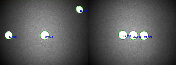
In the example below, the vision system is calibrated using the diameter of the white magnet images in the center. All of the white magnets have the same 20mm diameter but due to the distortion of the lens, the image provides results that have varied significantly. The right image displays the same physical setup with the magnets since they are closer to the image’s center the results are more accurate. Linear calibration is most commonly used for simple sortation applications where the parts can be easily distinguished from one another based on larger variation in sizes.
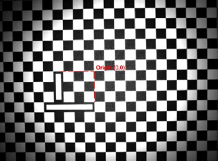
Non-Linear Calibration provides the most accurate results in real-world units. A checkerboard or a dot calibration plate is used in the calibration process. An example of a checkerboard with fiducial marking has been provided below. The fiducial marking provides the origin or center point reference within the calibrated vision system’s image.
Using the calibration plate allows the vision system to correct for lens and perspective distortion. Mitigating the error created by a distorted image, non-linear calibration enables the most accurate results across the entire image. Non-linear calibration is ideal for applications requiring strict measurement tolerance, and/or vision assisted guidance.
Machine vision systems collect and analyze data based on pixels within a digital image. Physical hardware changes can affect the sizing of a pixel with an image. Factors that affect the size of a pixel within a vision system are the working distance, the angle at which the camera is mounted, and lensing used. Any changes to the vision system that would affect the physical hardware setup would change the pixel size within the image captured.
When calibrating a vision system understanding what affects pixel size is important. If a change that would affect pixel size occurs after calibration, the calibration will become invalid and induce measurement/positioning error in the results from the vision system. Regularly validating a vision system’s output results helps maintain inspection tolerances for measurement and positioning tools.
Validating vision system results can be as simple as measuring a gauge block with known dimensions or as complex as running a test batch to confirm the vision system’s calibration meets tolerance requirements. If the vision system results are found outside of required tolerance, the vision system may need to be recalibrated as specified by the vision system developer or manufacturer.
If you have any questions on this or any other vision topic, please contact us at Automation, Inc. and we’d be happy to assist.

Comments